
Cloud Computing (5): Cloud Network Architecture and SDN
VPC, load balancers, CDN, SDN/NFV, and BGP -- a deep tour of cloud networking from packet to planet, with the production knobs that matter.

A cloud platform is essentially a network with attached computers. The compute layer scales by adding servers; the storage layer scales by adding disks; the network layer integrates these into a single, coherent system. Get the network right, and the rest of the stack feels effortless. Get it wrong — a missing route, a 5-tuple mismatch in a security group, or an under-provisioned load balancer — and the whole platform goes dark.
This article maps the cloud networking stack from the packet up: how a VPC carves an isolated network from shared infrastructure, what changes when load balancers move from L4 to L7, how a CDN converts geography into latency savings, why SDN reshaped the data center, and how BGP stitches it all together across regions.
What You Will Learn#
- VPC internals — subnets, route tables, gateways, endpoints, and the encapsulation that makes them isolated
- Load balancing — L4 vs L7, algorithms, health checks, sticky sessions, draining
- CDN architecture — edge PoPs, cache hierarchies, TLS termination, dynamic acceleration
- SDN — control / data plane split, OpenFlow / P4Runtime, NFV and service chains
- VPN, Direct Connect, and Transit Gateway — when to choose which connectivity model
- Security — security groups vs NACLs, flow logs, zero-trust micro-segmentation
- BGP and global routing — AS-paths, ECMP, anycast, multi-region failover
Prerequisites#
- IP addressing and CIDR notation
- Familiarity with at least one cloud console (AWS / GCP / Aliyun)
- Parts 1-3 of this series
Virtual Private Cloud (VPC)#
A VPC is a software-defined slice of the cloud provider’s physical network that behaves like your own private datacentre: you choose the IP space, draw the subnets, install the gateways and write the firewall rules. Behind the scenes the provider implements isolation through VXLAN (or a proprietary equivalent) — every packet carries a tenant tag so two customers can both use 10.0.0.0/16 without ever seeing each other’s traffic.
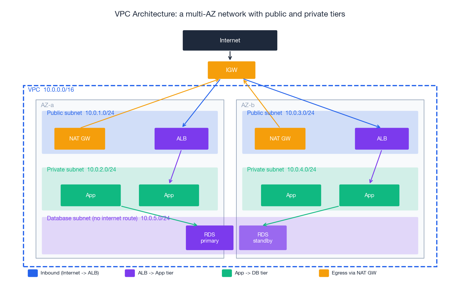
Anatomy of a production VPC#
The diagram above is a textbook 3-tier deployment. The pieces:
| Component | Layer | What it does | Free? |
|---|---|---|---|
| VPC | network | The 10.0.0.0/16 envelope. One per environment per region. | yes |
| Subnet | network | A CIDR carved out of the VPC, pinned to one AZ. Public/Private/Isolated by route table, not by name. | yes |
| Internet Gateway (IGW) | edge | Bidirectional NAT-free path to the public internet. One per VPC. | yes |
| NAT Gateway | egress | Lets private instances reach the internet outbound; blocks inbound. Per-AZ for HA. | hourly + GB |
| Route Table | control | Maps destination CIDR -> target (IGW, NAT, VPCe, peering, TGW). One per subnet. | yes |
| Security Group | instance FW | Stateful, allow-only, attached to ENIs. | yes |
| Network ACL | subnet FW | Stateless, allow + deny, ordered. Belt-and-braces with SGs. | yes |
| VPC Endpoint | data plane | Private path from VPC to a cloud service (S3, DynamoDB, Secrets Manager, …). | gateway free / interface hourly |
| Transit Gateway | hub | N-to-N VPC + VPN + Direct Connect interconnect. | hourly + GB |
The “public vs private subnet” distinction is purely about routes. A subnet whose route table contains 0.0.0.0/0 -> igw-... is public; a subnet whose default route is 0.0.0.0/0 -> nat-... is private; a subnet with no internet route at all is isolated. This sounds trivial but is the source of half of all “I cannot reach the internet from my Lambda” tickets.
Terraform: a real, multi-AZ VPC#
| |
Three production-relevant choices encoded above:
- One NAT GW per AZ. A single NAT GW is a per-AZ failure boundary; a region-wide NAT GW is a region-wide outage waiting to happen.
- Gateway endpoint for S3 / DynamoDB. Without it, every byte to S3 from a private subnet flows through the NAT GW and bills at $0.045/GB. The endpoint is free.
map_public_ip_on_launchonly on public subnets. Stops you from accidentally giving a private DB a public IP.
Connecting VPCs: peering, TGW, PrivateLink#
| Pattern | Topology | Best for | Caveats |
|---|---|---|---|
| VPC peering | point-to-point | 2-5 VPCs, simple intra-region | non-transitive: A↔B and B↔C does not give A↔C |
| Transit Gateway | hub-and-spoke | 5+ VPCs, VPN + DX integration, central inspection | hourly + per-GB charge |
| PrivateLink | service exposure | one VPC publishes a service to many consumer VPCs | one-way; no need to peer entire networks |
| Cloud WAN | global mesh | multi-region, multi-account meshes | newest, simplest at scale, costs accordingly |
The decision driver is mostly the topology you need, not the bandwidth — all of these can handle 10s of Gbps when sized correctly.
Load Balancing#
A load balancer turns a fleet into a service. It hides individual instance failures, spreads load, terminates TLS, and — in its L7 form — lets you reshape traffic by path, host or header without touching the apps.
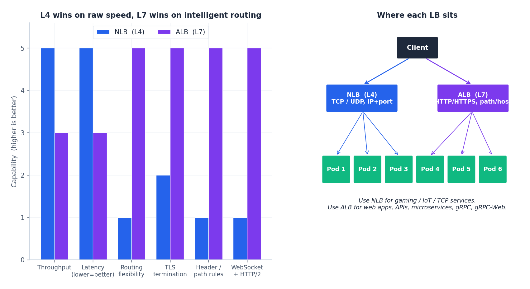
L4 vs L7#
| Feature | Network LB (L4) | Application LB (L7) |
|---|---|---|
| Operates on | TCP / UDP / TLS | HTTP / HTTPS / gRPC |
| Routing decision | 5-tuple (src IP/port, dst IP/port, protocol) | path, host, header, cookie, JWT claim |
| Latency added | tens of µs | low ms |
| Throughput per LB | 100s of Gbps | 10s of Gbps |
| TLS termination | optional (passthrough or terminate) | almost always terminate |
| WebSocket / HTTP/2 / gRPC | passthrough only | first-class |
| Source IP preservation | yes (with proxy protocol) | via X-Forwarded-For |
| Best for | Game servers, IoT, MQTT, low-level TCP | Web apps, microservices, public APIs |
A practical pattern in modern stacks: L4 (NLB) -> L7 (Envoy/ALB) -> services. The L4 layer absorbs DDoS and gives you a stable anycast IP; the L7 layer does smart routing and authentication. Each layer does one thing well.
Algorithms#
| |
For most stateless web traffic, power-of-two-choices (P2C) is empirically near-optimal and trivial to implement. For cache-sensitive workloads (anything in front of a key-value store), use a consistent or Maglev hash so the same key keeps hitting the same backend.
ALB with path + host routing (Terraform)#
| |
The non-obvious knobs:
deregistration_delayshould match your application’s graceful-shutdown window. The default 300 s blocks deploys; setting it lower than your in-flight request timeout drops connections.drop_invalid_header_fields = truemitigates HTTP request-smuggling attacks (CVE-2019-18860 class).enable_cross_zone_load_balancingensures even spread when AZs have unequal target counts. Off by default on NLB, on by default on ALB.
Health checks that do not lie#
A health check that hits / and runs a database query does tell you when the database is down — but it also marks the entire fleet unhealthy on the first DB blip, taking the whole site offline. The pattern that survives production:
/livez— “the process is alive” (no dependencies). LB checks this./readyz— “this instance can serve traffic right now” (cache warmed, DB pool open). Kubernetes checks this.- Application metrics, traces, and logs check the rest — not the load balancer.
Content Delivery Networks (CDN)#
A CDN is geography turned into a cache. Static content is replicated to edge PoPs near users; the origin (often an S3 bucket) is hit only on a cache miss. Latency drops from 200 ms to under 30 ms; origin egress drops by 10x or more.
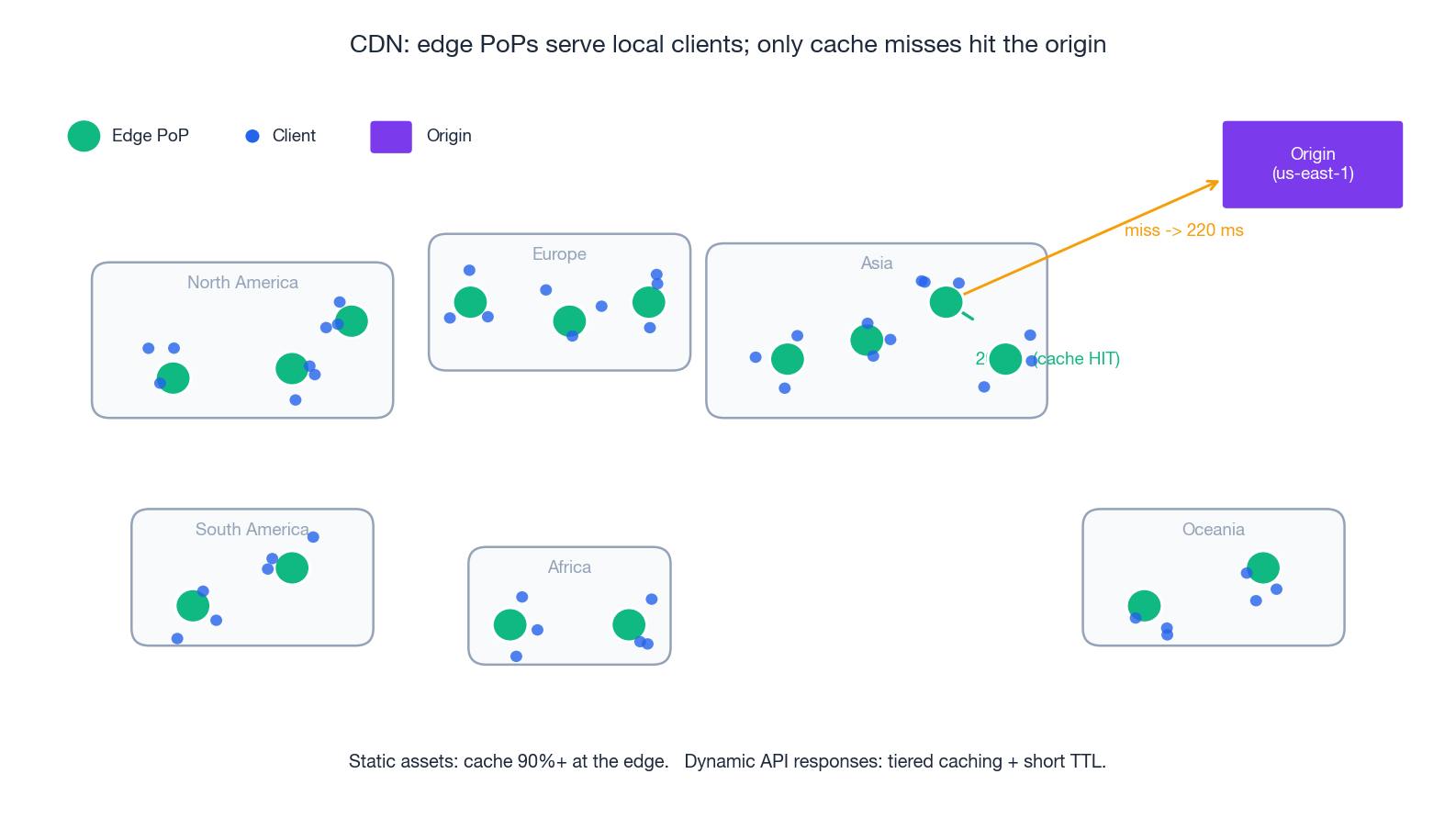
What actually happens on a request#
- DNS — the user resolves
cdn.example.comto an anycast IP that lands at the closest healthy PoP. - TLS termination — the TLS handshake completes at the edge (much shorter RTT) and the PoP holds a session ticket.
- Cache lookup — the PoP keys on URL + Vary headers. On HIT, return immediately.
- MISS path — the PoP fetches from a parent (regional cache) which may itself fetch from origin (the hierarchical/tiered cache reduces origin load even for unique content).
- Cache fill — the PoP stores the response per its TTL (
Cache-Control: max-age,s-maxage,stale-while-revalidate).
Cache headers that work#
| |
Three rules of thumb:
immutableis the single biggest win on static assets (no revalidation traffic at all).stale-while-revalidatelets the CDN serve a stale copy while it asynchronously refreshes — origin pain becomes invisible to users.- Vary on the bare minimum.
Vary: Accept-Encodingis fine;Vary: User-Agentblows up the cache key space and your hit ratio.
Beyond static: dynamic acceleration#
Modern CDNs also accelerate uncacheable traffic. The mechanisms:
- TLS / TCP termination at the edge cuts the client-side handshake from
4 × RTT_to_originto4 × RTT_to_edge. - Pre-warmed long-haul connections between PoPs and origin reuse keepalive (no re-handshake per request).
- Anycast DNS + BGP optimisation routes the client to the lowest-latency PoP, not just the closest by mileage.
The combination — CloudFront’s “CloudFront Functions”, Aliyun DCDN, Cloudflare Workers — moves the line between “static” and “dynamic” further into the application than most teams realise.
Software-Defined Networking (SDN)#
Traditional networks bound the control (routing, ACLs, QoS) tightly to each device. SDN separates the control plane (decisions, programmable from above) from the data plane (line-rate forwarding). The result is a network that you can manage like software: declarative, version-controlled, observable.
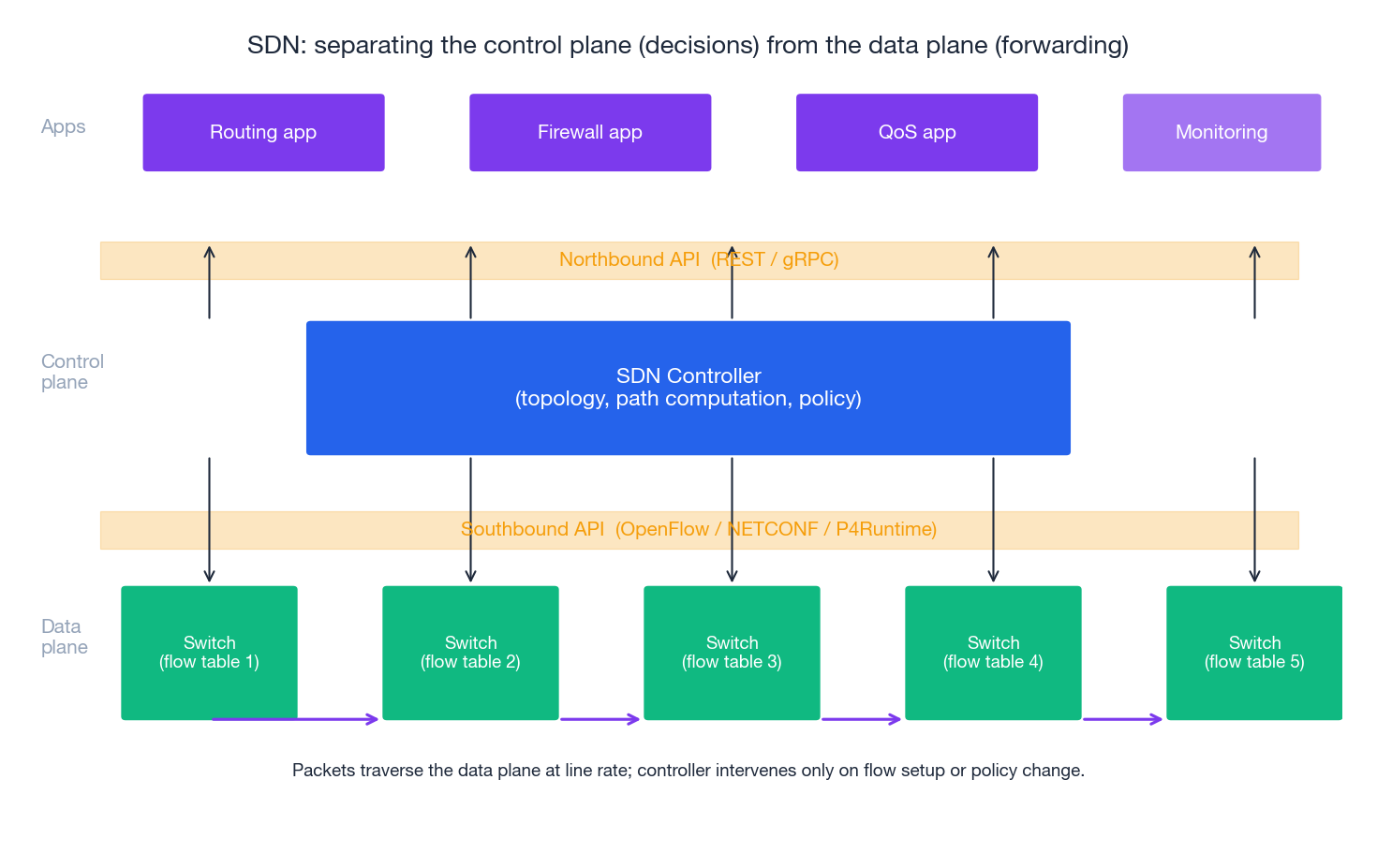
The split#
| Plane | Responsibility | Implementation |
|---|---|---|
| Control plane | Build the topology, compute paths, enforce policy, expose APIs | Logically centralised controller (ONOS, OpenDaylight, hyperscaler proprietary) |
| Data plane | Match -> action on every packet at line rate | ASIC switches with a flow table, or eBPF/XDP/DPDK in software |
| Southbound API | Controller pushes flow rules to switches | OpenFlow 1.3+, NETCONF/YANG, gNMI, P4Runtime |
| Northbound API | Apps program the controller | REST / gRPC, GraphQL |
Inside a hyperscaler’s region, everything is SDN: Hyper-V Virtual Switch, Open vSwitch, Cisco ACI, AWS’s “Mapping Service” + “Hyperplane” implement what you experience as a VPC. Your security-group rules are compiled into ACL entries pushed to the host’s vswitch on the path your packet takes — not enforced at the destination instance.
Why operators love it#
- Centralised intent. “All traffic from PCI-tagged subnets must pass through inspection” is one policy, applied everywhere, instead of 200 device configs.
- Traffic engineering. A controller seeing the whole topology can route around congestion that distributed routing protocols (OSPF, IS-IS) react to with a 30-second delay.
- Programmable packet processing. P4 lets the data plane parse new protocols (e.g. SRv6, custom in-band telemetry) without an ASIC respin.
- Fast failure recovery. SDN-precomputed alternate paths + BFD failure detection reduces MTTR to milliseconds.
Network Functions Virtualisation (NFV)#
NFV is SDN’s sibling: replace dedicated network appliances with software running on commodity x86 servers. A firewall, a load balancer, a WAN optimiser — each becomes a VNF that you can spin up, scale, and chain like any other workload.
| |
A representative VNF — HAProxy as the load balancer in a service chain:
| |
Service chaining (sometimes called service function chaining, SFC) is the topology by which traffic walks through the VNFs in order. In a Kubernetes mesh, this is what an Envoy sidecar + mesh policy does for east-west traffic.
Hybrid connectivity: VPN, Direct Connect, Transit Gateway#
Most enterprises live in hybrid topologies: cloud workloads need to reach on-prem databases, identity providers, or partner networks. There are three layers of connectivity tooling.
VPN vs Direct Connect#
| Feature | Site-to-site VPN | Direct Connect / Express Connect / Cloud Interconnect |
|---|---|---|
| Path | Encrypted tunnel over the public internet | Dedicated physical fibre to a provider POP |
| Bandwidth | up to ~10 Gbit/s, jitter-prone | 1 / 10 / 100 Gbit/s, deterministic |
| Latency | variable (tens of ms + jitter) | low, single-digit ms within metro, stable |
| Setup time | minutes | weeks (carrier provisioning) |
| Cost | hourly + per-GB egress | port hourly + per-GB egress (cheaper at scale) |
| Encryption | IPsec mandatory | optional MACsec; usually you run IPsec on top for confidentiality |
| Best for | low / variable volume, dev environments | production data flows, low-latency sync, regulatory needs |
A common layered approach: DX as the primary with a VPN as the encrypted backup that activates on DX failure. Both terminate on the same Virtual Private Gateway / Transit Gateway.
Transit Gateway#
A Transit Gateway (TGW) is the regional hub: every VPC, every VPN, every DX connection attaches once and gains reachability to everything else, governed by route tables on the TGW itself. It replaces the N²-peering problem with N attachments.
| |
The pattern — disable default association/propagation, then write the routes you want — is how you turn a TGW from a flat-mesh footgun into an enforceable segmentation boundary.
Security in the network#
Security Groups vs Network ACLs#
| Feature | Security Group | Network ACL |
|---|---|---|
| Attached to | ENI / instance | Subnet |
| State | Stateful (return traffic auto-allowed) | Stateless (must allow both directions) |
| Rules | Allow only | Allow + Deny |
| Default | Deny all inbound, allow all outbound | Allow all both ways |
| Rule evaluation | All rules union | First match wins (numeric order) |
| Quota (AWS) | 60 inbound + 60 outbound, 5 SGs per ENI | 20 inbound + 20 outbound rules per NACL |
| Best for | App-to-app authorisation | Blast-radius limits, deny-listing IPs |
The robust pattern is SG-to-SG references: instead of opening port 3306 from a CIDR, open port 3306 from aws_security_group.app.id. The rule remains correct as the app fleet scales and IPs churn; auditors see intent, not infrastructure.
| |
VPC Flow Logs#
Flow Logs record every accepted/rejected 5-tuple to S3 or CloudWatch. Three queries you will run within a week of enabling them:
| |
Zero trust at the network layer#
The “soft chewy interior” model — a hard perimeter, trusted internal network — is gone. Modern designs assume the network is hostile and enforce identity per request. Practical building blocks:
- mTLS everywhere (service-to-service via a mesh: Istio, Linkerd, App Mesh).
- Short-lived workload identity (SPIFFE/SPIRE, IAM Roles for Service Accounts, GCP Workload Identity).
- Per-flow policy evaluated by the SDN (security groups + Cilium NetworkPolicies + service-mesh L7 RBAC layered together).
BGP and global routing#
When a request leaves your region and crosses the public internet — or when you fail over from one region to another — the system that gets it there is BGP, the Border Gateway Protocol. BGP is the routing protocol between autonomous systems (ASes); within a region your provider runs OSPF or IS-IS, but the moment you step out, BGP is in charge.
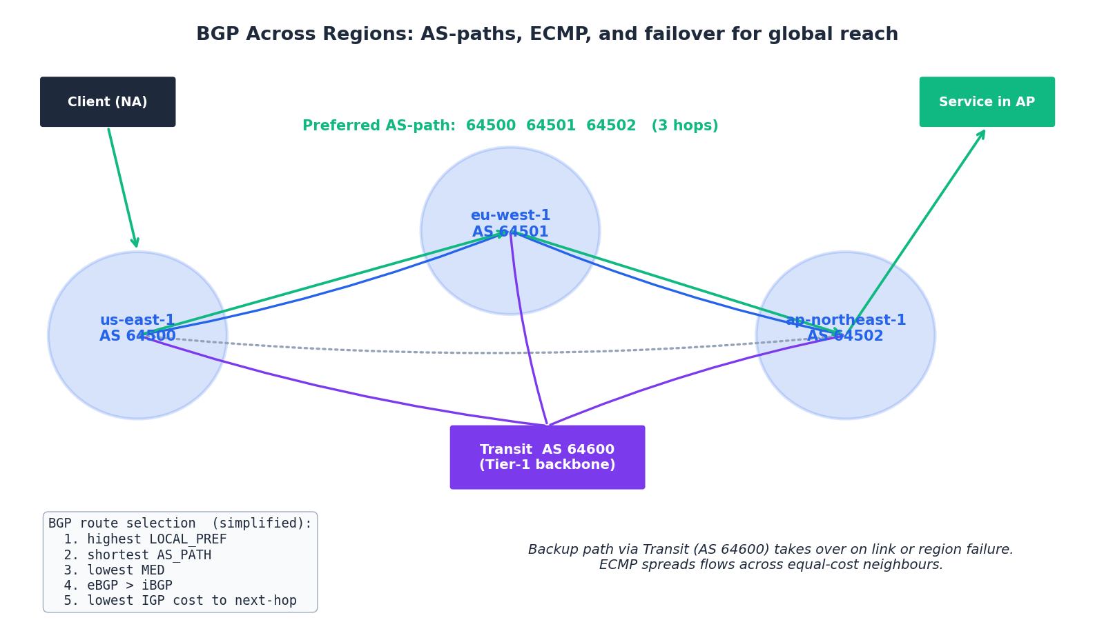
The route-selection algorithm (simplified)#
Given multiple paths to the same prefix, BGP picks one by walking down a long tiebreak list. The first five rungs cover 99% of cases:
- Highest LOCAL_PREF — “internal preference”; how we want to leave our network. Operator-set.
- Shortest AS_PATH — fewer ASes to traverse.
- Lowest MED — “I’d prefer you enter my AS this way”; honoured between peers, not always between providers.
- eBGP > iBGP — prefer routes learned from external peers over internal.
- Lowest IGP cost to the next hop — shortest internal path to the chosen exit.
ECMP and anycast#
- ECMP (Equal-Cost Multi-Path) — when several paths tie on all the above, hash the 5-tuple of each flow and spread them across the equal-cost neighbours. ECMP is how a 100 Gbit/s logical link is built from ten 10 Gbit/s physical links, and how a multi-region anycast service spreads load across its PoPs.
- Anycast — announce the same IP from many locations; BGP delivers each user to the topologically closest one. Anycast is the foundation of every CDN, every DNS root, every public DoH resolver.
Multi-region failover#
A common pattern for global services:
- Primary region serves writes; secondary regions serve reads.
- The DNS name is anycast or a Route 53 / Aliyun GTM failover record set keyed off health checks.
- Database replication is async cross-region; on failover the standby is promoted (RPO of seconds to minutes).
- On recovery, traffic is manually shifted back — automatic flap-back has burned almost everyone who has tried it.
The BGP details rarely intrude on the application — but when something is mis-announced upstream (the Facebook 2021 outage or any of the hundreds of route leaks per year) every layer above goes dark. RPKI route-origin validation and a careful prefix list at the ingress edge are mandatory hygiene at any meaningful scale.
Troubleshooting in production#
The triage order#
When traffic is broken, walk up from the wire:
- Reachability — can the source ARP/ND the gateway?
ip neigh,arping. If not, it is L2 / SG / NACL. - Routing — does the route table have a path?
aws ec2 describe-route-tables,ip route. - Filters — is the SG / NACL allowing the 5-tuple? Check both directions if NACL is involved.
- DNS — is the name resolving to the IP you think?
dig +short, beware of split-horizon DNS. - TLS —
openssl s_client -connect host:443 -servername host. Half of “API down” is a stale cert. - Application —
curl -vvv https://.... Log shows200 OK? It’s not the network.
The Swiss-army CLI#
| |
The five most expensive misconfigurations#
| Symptom | Usual cause | Fix |
|---|---|---|
| Lambda in VPC cannot reach the internet | Default route missing or NAT GW down | 0.0.0.0/0 -> nat-... on the function’s subnet |
| Sudden NAT GW bill spike | App pulled large object from S3 over NAT instead of via Gateway Endpoint | Add aws_vpc_endpoint.s3 |
| Random TCP resets after seconds | SG / NACL allows new flows but stateful tracking dropped (idle timeout) | Tune keepalive, increase tcp-keepalive-time |
| Cross-AZ data transfer cost dwarfs compute | LB cross-zone off, or services not AZ-aware | Enable cross-zone LB; topology-aware routing in K8s |
| Asymmetric routing on multi-homed VPC | SG stateful tracking sees only one direction | Route both directions through the same TGW attachment |
FAQ#
Q: Should we run our own load balancer (HAProxy / NGINX) or use the cloud LB?
Use the cloud LB unless you have a specific reason not to (custom routing logic, sticky on a header the cloud LB does not support, tight latency budget). Cloud LBs are HA, auto-scaling, integrated with TLS / WAF / IAM; you get back the engineer who would have run HAProxy.
Q: NLB or ALB?
ALB for HTTP/gRPC services (path/host routing, OIDC auth, redirects). NLB for non-HTTP TCP/UDP, for static-IP requirements (each NLB has a per-AZ EIP), or when you need extreme PPS.
Q: How many subnets per VPC?
At least one public + one private + one DB subnet per AZ. A 3-AZ VPC therefore has 9 subnets. More if you separate by tier (web/app/db/mgmt) or by sensitivity (PCI/non-PCI). Keep /16 per VPC and /22-/24 per subnet so you have room to grow.
Q: When does my workload need its own SDN controller (vs the cloud’s)?
Almost never on the cloud — you are renting the controller and you cannot replace it. On-prem with OpenStack or VMware NSX, yes. Edge / 5G operators who build their own DC fabric, yes. Most application teams should not even think about SDN below the VPC abstraction.
Cloud Computing 8 parts
- 01 Cloud Computing (1): Fundamentals and Architecture
- 02 Cloud Computing (2): Virtualization Technology Deep Dive
- 03 Cloud Computing (3): Cloud-Native and Container Technologies
- 04 Cloud Computing (4): Cloud Storage Systems and Distributed Architecture
- 05 Cloud Computing (5): Cloud Network Architecture and SDN you are here
- 06 Cloud Computing (6): Cloud Security and Privacy Protection
- 07 Cloud Computing (7): Cloud Operations and DevOps Practices
- 08 Cloud Computing (8): Multi-Cloud and Hybrid Architecture