
Ordinary Differential Equations (4): The Laplace Transform
The engineer's secret weapon: turn differential equations into algebra with the Laplace transform. Learn the key properties, partial fractions, transfer functions, and PID control basics.
The Laplace transform turns calculus into algebra. Instead of grinding through integration, guessing trial solutions, and bolting on initial conditions at the end, you transform the entire ODE — equation, forcing, and initial data — into a single polynomial equation in a complex variable $s$ . You solve it like a high-school problem, then transform back. Along the way, the shape of the solution becomes geometry: poles in the left half of the complex plane decay, poles on the right blow up, poles on the imaginary axis ring forever. This chapter develops that picture from first principles and connects it to the engineering tools — transfer functions, Bode plots, PID control — that made the Laplace transform the lingua franca of dynamics.

What You Will Learn#
- The definition and the intuition behind $e^{-st}$ as a “decay probe”
- The differentiation property — the key that converts an ODE into algebra
- A small transform table you can use to invert almost everything in this course
- Partial fraction decomposition for distinct, repeated, and complex poles
- Transfer functions, the pole–zero picture, and the geometric stability criterion
- Step and impulse responses, and how they encode the system completely
- Bode plots and the time vs frequency duality
- PID control: how P, I, and D each fix one weakness of the others
Prerequisites#
- Chapters 1–3: first- and second-order ODEs and the superposition principle
- Partial fractions from algebra/calculus
- Complex numbers basics ($a + bi$ , magnitude, phase)
- Familiarity with the integral $\int_0^\infty e^{-st}\,dt$
Why the Laplace transform exists#
$$RC\,V_c'(t) + V_c(t) = V_s(t), \qquad V_c(0) = V_0.$$If $V_s$ is a constant, you can solve this with an integrating factor in two lines. But the moment $V_s$ becomes a switched-on step, a brief impulse, a ramp, or some piecewise waveform from a real signal generator, the elementary methods grow tedious. You end up with a forest of integration constants, side-condition matching, and case analysis.
The Laplace transform offers a single workflow that handles all of these:
- Transform both sides of the ODE — derivatives become polynomials in $s$ , and the initial conditions are absorbed automatically.
- Solve the resulting algebraic equation for $Y(s)$ .
- Inverse transform back to $y(t)$ using a small table.
The bookkeeping disappears, leaving a clean separation: who drives the system (the transform of the input), what the system does to it (the transfer function), and how it started (the initial conditions, already woven in).

Definition and the core transform table#
The forward transform#
$$F(s) = \mathcal{L}\{f(t)\} = \int_0^\infty f(t)\,e^{-st}\,dt.$$Intuition. Think of $e^{-st}$ as a probe that, for each complex frequency $s$ , asks: how much of $f$ survives if I weight it by an exponential that decays at rate $\operatorname{Re}(s)$ ? When $s$ is large and positive, the probe sees only the behaviour of $f$ near $t = 0$ . When $\operatorname{Re}(s)$ is small, it sees the long-term tail. The full function $F(s)$ is the answer at every $s$ at once — a fingerprint of $f$ .
A working transform table#
| $f(t)$ | $F(s) = \mathcal{L}\{f(t)\}$ | Region of convergence |
|---|---|---|
| $1$ (or $u(t)$ ) | $1/s$ | $\operatorname{Re}(s) > 0$ |
| $t^n$ | $n!/s^{n+1}$ | $\operatorname{Re}(s) > 0$ |
| $e^{at}$ | $1/(s-a)$ | $\operatorname{Re}(s) > a$ |
| $\sin\omega t$ | $\omega/(s^2+\omega^2)$ | $\operatorname{Re}(s) > 0$ |
| $\cos\omega t$ | $s/(s^2+\omega^2)$ | $\operatorname{Re}(s) > 0$ |
| $e^{at}\sin\omega t$ | $\omega/((s-a)^2+\omega^2)$ | $\operatorname{Re}(s) > a$ |
| $e^{at}\cos\omega t$ | $(s-a)/((s-a)^2+\omega^2)$ | $\operatorname{Re}(s) > a$ |
| $\delta(t)$ (impulse) | $1$ | all $s$ |
| $u(t-a)$ (delayed step) | $e^{-as}/s$ | $\operatorname{Re}(s) > 0$ |
This is enough to invert nearly every problem in the chapter.
Two derivations from the definition#
$$\int_0^\infty e^{-st}\,dt = \left[-\frac{1}{s}\,e^{-st}\right]_0^\infty = \frac{1}{s}, \qquad \operatorname{Re}(s) > 0.$$ $$\int_0^\infty e^{at}\,e^{-st}\,dt = \int_0^\infty e^{-(s-a)t}\,dt = \frac{1}{s-a}, \qquad \operatorname{Re}(s) > a.$$The same trick — fold $e^{at}$ into the kernel — is what makes the frequency-shift property below trivially obvious.
The properties that do all the work#
Linearity#
$$\mathcal{L}\{a f + b g\} = a F(s) + b G(s).$$Differentiation — the key to the whole subject#
$$\mathcal{L}\{f'(t)\} = sF(s) - f(0),$$ $$\mathcal{L}\{f''(t)\} = s^2 F(s) - s f(0) - f'(0),$$ $$\mathcal{L}\{f^{(n)}(t)\} = s^n F(s) - s^{n-1} f(0) - \cdots - f^{(n-1)}(0).$$Why this matters. Differentiation in $t$ becomes multiplication by $s$ , and the initial conditions appear as part of the formula, not as side constraints to be matched later. An $n$ -th order linear ODE turns into an $n$ -th degree polynomial equation in $s$ that already knows about $y(0), y'(0), \dots$ .
$$\int_0^\infty f'(t)\,e^{-st}\,dt = \left[f(t)\,e^{-st}\right]_0^\infty + s\int_0^\infty f(t)\,e^{-st}\,dt = sF(s) - f(0),$$provided $f(t)\,e^{-st}\to 0$ at infinity, which is the meaning of the region of convergence.
Frequency shift#
$$\mathcal{L}\{e^{at}f(t)\} = F(s-a).$$Multiplying by $e^{at}$ in the time domain shifts the entire transform by $a$ . This is why every “damped” entry in the table is just an undamped entry with $s\to s-a$ .
Time shift (delay)#
$$\mathcal{L}\{f(t-a)\,u(t-a)\} = e^{-as}F(s), \qquad a > 0.$$A delay in time becomes a multiplicative phase $e^{-as}$ in the $s$ -domain. Use the gate $u(t-a)$ to make sure you are transforming the delayed-and-truncated signal, not the original.
Convolution#
$$\mathcal{L}\{(f * g)(t)\} = F(s)\,G(s), \qquad (f * g)(t) = \int_0^t f(\tau)\,g(t-\tau)\,d\tau.$$In the time domain, the response of an LTI system to an input is a convolution; in the $s$ -domain it is just a product. This is the algebraic statement that makes block diagrams work.
Final value theorem#
$$\lim_{t\to\infty} f(t) = \lim_{s\to 0} sF(s),$$provided the limit exists and all poles of $sF(s)$ lie in the open left half-plane. Use it to read steady-state values straight off $Y(s)$ , without inverting.
Solving ODEs: the workflow in two examples#
First-order with an exponential forcing#
Solve $y' + 2y = e^{-t}$ , $y(0) = 1$ .
$$sY(s) - 1 + 2Y(s) = \frac{1}{s+1}.$$ $$(s+2)Y(s) = 1 + \frac{1}{s+1}, \qquad Y(s) = \frac{1}{s+2} + \frac{1}{(s+1)(s+2)}.$$ $$Y(s) = \frac{1}{s+2} + \frac{1}{s+1} - \frac{1}{s+2} = \frac{1}{s+1}.$$ $$\boxed{\; y(t) = e^{-t}.\;}$$Verify. $y' + 2y = -e^{-t} + 2e^{-t} = e^{-t}$ , and $y(0) = 1$ . Done.
Second-order with resonance#
Solve $y'' + \omega_0^2\,y = \cos\omega_0 t$ , with $y(0) = y'(0) = 0$ .
$$s^2 Y + \omega_0^2 Y = \frac{s}{s^2 + \omega_0^2}, \qquad Y(s) = \frac{s}{(s^2 + \omega_0^2)^2}.$$ $$y(t) = \frac{t}{2\omega_0}\,\sin\omega_0 t.$$The crucial feature is the explicit factor of $t$ . Algebraically, it comes from the repeated pole pair at $s = \pm j\omega_0$ : a higher-multiplicity pole produces a polynomial-times-sinusoid in time. Physically, it means the amplitude grows without bound — this is resonance.

Partial fractions: the only technique you really need#
Once you have $Y(s)$ as a rational function, almost all of the inversion work is splitting it into a sum of pieces that match table entries.
Distinct real poles#
$$\frac{P(s)}{(s-a)(s-b)} = \frac{A}{s-a} + \frac{B}{s-b}.$$Use the cover-up rule: $A$ equals $P(s)/(s-b)$ evaluated at $s = a$ . (Geometrically, you “cover” the $(s-a)$ factor and plug in the pole.)
Repeated poles#
$$\frac{P(s)}{(s-a)^3} = \frac{A_1}{s-a} + \frac{A_2}{(s-a)^2} + \frac{A_3}{(s-a)^3}.$$Each multiplicity-$k$ pole produces a term of the form $t^{k-1}\,e^{at}/(k-1)!$ in the time domain.
Complex conjugate poles#
$$\frac{B s + C}{(s-\alpha)^2 + \beta^2}\;\xrightarrow{\;\mathcal{L}^{-1}\;}\; e^{\alpha t}\big(B \cos\beta t + D \sin\beta t\big),$$where $D = (C + \alpha B)/\beta$ after rewriting the numerator as $B(s-\alpha) + (C + \alpha B)$ .

Transfer functions and the geometry of stability#

Definition#
$$H(s) \;=\; \frac{Y(s)}{U(s)}\quad\text{at zero initial conditions.}$$$H(s)$ is the transfer function. It depends only on the system, not on what you feed in or how it started.
$$H(s) = \frac{1}{RCs + 1} = \frac{1}{\tau s + 1}, \qquad \tau = RC.$$A single real pole at $s = -1/\tau$ .
Poles, zeros, and stability#
- Zeros are values of $s$ where $H(s) = 0$ (numerator roots).
- Poles are values of $s$ where $H(s) \to \infty$ (denominator roots).
The pole picture decides everything about the unforced response. Each pole contributes one mode to $\mathcal{L}^{-1}\{H(s)\}$ :
| Pole location | Time-domain mode | Behaviour |
|---|---|---|
| Real, $s = -a$ with $a > 0$ | $e^{-at}$ | decays to zero |
| Real, $s = a > 0$ | $e^{at}$ | grows without bound — unstable |
| Complex pair $\alpha \pm j\beta$ , $\alpha < 0$ | $e^{\alpha t}(\cos\beta t,\sin\beta t)$ | damped oscillation |
| Pure imaginary $\pm j\beta$ | $\cos\beta t,\,\sin\beta t$ | undamped oscillation |
| Complex pair, $\alpha > 0$ | $e^{\alpha t}(\cos\beta t,\sin\beta t)$ | growing oscillation — unstable |
Geometric stability criterion. The system is asymptotically stable if and only if every pole of $H(s)$ lies strictly in the left half-plane $\operatorname{Re}(s) < 0$ .

Step and impulse responses#
The two canonical probes deserve their own names.
- Impulse response. $h(t) = \mathcal{L}^{-1}\{H(s)\}$ — what comes out when the input is a Dirac delta.
- Step response. $s(t) = \mathcal{L}^{-1}\{H(s)/s\}$ — what comes out when the input is a unit step.
- Identity. $h(t) = s'(t)$ . The two encode the same information; a step is the integral of a delta.
Once you know $h(t)$ , the response to any input is the convolution $y(t) = (h * u)(t)$ . Equivalently, $Y(s) = H(s)\,U(s)$ .
Two windows on the same system: time and frequency#
Substituting $s = j\omega$ in $H(s)$ gives the frequency response $H(j\omega)$ . The magnitude $|H(j\omega)|$ tells you how much each sinusoidal frequency is amplified; the phase $\arg H(j\omega)$ tells you how much it is delayed. Plotted on a log–log scale, these are the Bode plots.
$$H(s) = \frac{\omega_n^2}{s^2 + 2\zeta\omega_n s + \omega_n^2},$$the damping ratio $\zeta$ controls everything. With $\zeta < 1$ the poles are complex and the step response overshoots and rings; with $\zeta = 1$ they coalesce into a double real pole at $-\omega_n$ and the response rises as fast as it can without overshoot; with $\zeta > 1$ the poles split apart on the real axis and the response is sluggish.

| |
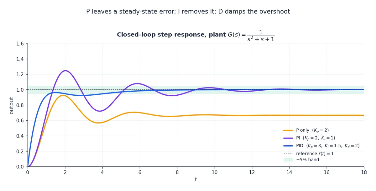
PID control: each term fixes what the others cannot#
$$u(t) = K_p\,e(t) + K_i\!\int_0^t e(\tau)\,d\tau + K_d\,\frac{de}{dt}.$$ $$C(s) = K_p + \frac{K_i}{s} + K_d\,s.$$Each term covers a specific failure mode of the others.
| Term | What it does | Strength | Failure mode |
|---|---|---|---|
| P (proportional) | Reacts to the present error | Fast initial correction | Leaves a steady-state error |
| I (integral) | Accumulates past error | Drives steady-state error to zero | Slows the loop, can cause oscillation |
| D (derivative) | Predicts where the error is going | Damps overshoot | Amplifies measurement noise |
Tuning $K_p, K_i, K_d$ moves the closed-loop poles around the $s$ -plane. The art is to push them deep into the left half-plane (for stability and speed) without making the imaginary parts too large (which would cause ringing).
Python practice: symbolic and numerical#
Symbolic transforms with SymPy#
| |
Pole–zero analysis with SciPy#
| |
Summary#
The five-step workflow#
- Transform both sides of the ODE; absorb the initial conditions.
- Solve algebraically for $Y(s)$ .
- Decompose $Y(s)$ into partial fractions.
- Invert term by term using the table.
- Verify by substituting into the original ODE.
The properties to memorise#
| Property | Formula | Where it earns its keep |
|---|---|---|
| Differentiation | $\mathcal{L}\{f'\} = sF(s) - f(0)$ | Turns ODEs into algebra |
| Frequency shift | $\mathcal{L}\{e^{at}f\} = F(s-a)$ | Damped oscillators, exponential forcing |
| Time shift | $\mathcal{L}\{f(t-a)u(t-a)\} = e^{-as}F(s)$ | Delays and switched inputs |
| Convolution | $\mathcal{L}\{f * g\} = F(s)\,G(s)$ | Block diagrams, system response |
| Final value | $\lim_{t\to\infty} f = \lim_{s\to 0} sF(s)$ | Steady-state without inverting |
The one-sentence picture#
Linear time-invariant systems live naturally in the $s$ -plane: their poles are their genome, the left half-plane is “stable”, and the operations you do in time become arithmetic in $s$ .
Exercises#
Basic
- Find $\mathcal{L}\{t^2 e^{-3t}\}$ and $\mathcal{L}\{e^{2t}\sin 3t\}$ using the frequency-shift property.
- Invert $F(s) = \dfrac{2s+1}{(s+1)(s+3)}$ .
- Solve $y' + 3y = e^{-2t}$ with $y(0) = 1$ using Laplace transforms; verify your answer.
- Prove the differentiation property $\mathcal{L}\{f'\} = sF(s) - f(0)$ from the definition by integration by parts, and state precisely the condition you need at $t \to \infty$ .
Advanced
- Solve $y'' + 4y = \delta(t)$ with $y(0) = y'(0) = 0$ , and explain why the impulse response equals $\tfrac{1}{2}\sin 2t$ .
- For $H(s) = \dfrac{10}{s^2 + 2s + 10}$ , find the poles, the impulse response, and the step response. Identify $\zeta$ and $\omega_n$ .
- Use the final value theorem to find $\lim_{t\to\infty} y(t)$ when $Y(s) = \dfrac{5}{s(s^2+3s+2)}$ , and check that the theorem’s hypotheses are satisfied.
Programming
- Plot Bode magnitude and phase for $H(s) = \dfrac{100}{s^2 + 10s + 100}$ . Estimate the resonant peak from the plot and compare with $\omega_n\sqrt{1 - 2\zeta^2}$ .
- Simulate the step response of a system with pure time delay, $H(s) = \dfrac{e^{-s}}{s+1}$
, using SciPy’s
lsimafter expanding the delay with a Padé approximation.
References#
- Kreyszig, E. Advanced Engineering Mathematics (10th ed.), Wiley (2011) — Chapter 6 is the standard textbook treatment of the Laplace transform.
- Ogata, K. Modern Control Engineering (5th ed.), Pearson (2010) — pole–zero analysis, Bode plots, and PID tuning in depth.
- Oppenheim, A. V. & Willsky, A. S. Signals and Systems (2nd ed.), Prentice Hall (1997) — the engineering-signals viewpoint and convolution.
- Strang, G. Differential Equations and Linear Algebra, Wellesley-Cambridge (2014) — a more geometric introduction.
- SciPy:
scipy.signal— Python tools for transfer functions, step/impulse responses, and Bode plots.
This is Part 4 of the 18-part series on Ordinary Differential Equations.
- Part 1: Origins and Intuition
- Part 2: First-Order Methods
- Part 3: Higher-Order Linear Theory
- Part 4: The Laplace Transform (current)
- Part 5: Power Series and Special Functions
- Part 6: Linear Systems and the Matrix Exponential
- Part 7: Stability Theory
- Part 8: Nonlinear Systems and Phase Portraits
- Part 9: Chaos Theory and the Lorenz System
- Part 10: Bifurcation Theory
- Part 11: Numerical Methods
- Part 12: Boundary Value Problems
- Part 13: Introduction to PDEs
- Part 14: Epidemic Models
- Part 15: Population Dynamics
- Part 16: Fundamentals of Control Theory
- Part 17: Physics and Engineering Applications
- Part 18: Frontiers and Series Finale
ODE Foundations 18 parts
- 01 Ordinary Differential Equations (1): Origins and Intuition
- 02 Ordinary Differential Equations (2): First-Order Methods
- 03 Ordinary Differential Equations (3): Higher-Order Linear Theory
- 04 Ordinary Differential Equations (4): The Laplace Transform you are here
- 05 Ordinary Differential Equations (5): Power Series and Special Functions
- 06 Ordinary Differential Equations (6): Linear Systems and the Matrix Exponential
- 07 Ordinary Differential Equations (7): Stability Theory
- 08 Ordinary Differential Equations (8): Nonlinear Systems and Phase Portraits
- 09 Ordinary Differential Equations (9): Chaos Theory and the Lorenz System
- 10 Ordinary Differential Equations (10): Bifurcation Theory
- 11 Ordinary Differential Equations (11): Numerical Methods
- 12 Ordinary Differential Equations (12): Boundary Value Problems
- 13 Ordinary Differential Equations (13): Introduction to Partial Differential Equations
- 14 Ordinary Differential Equations (14): Epidemic Models and Epidemiology
- 15 Ordinary Differential Equations (15): Population Dynamics
- 16 Ordinary Differential Equations (16): Fundamentals of Control Theory
- 17 Ordinary Differential Equations (17): Physics and Engineering Applications
- 18 Ordinary Differential Equations (18): Frontiers and Series Finale


